The RS-232 serial communication protocol is a standard protocol used in asynchronous serial communication. It is the primary protocol used over modem lines. It is the protocol used by the MicroStamp11 when it communicates with a host PC.
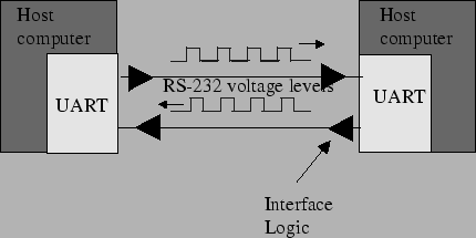
Figure 23 shows the relationship between the
various components in a serial ink. These components are the UART, the serial channel, and the interface logic. An interface chip
known as the universal asynchronous receiver/transmitter or UART is used to implement serial data transmission. The UART sits
between the host computer and the serial channel. The serial
channel is the collection of wires over which the bits are
transmitted. The output from the UART is a standard TTL/CMOS logic
level of 0 or 5 volts. In order to improve bandwidth, remove noise,
and increase range, this TTL logical level is converted to an RS-232
logic level of ![]() or
or ![]() volts before being sent out on the
serial channel. This conversion is done by the interface logic shown
in figure 23. In your system the interface logic
is implemented by the comm stamp.
volts before being sent out on the
serial channel. This conversion is done by the interface logic shown
in figure 23. In your system the interface logic
is implemented by the comm stamp.
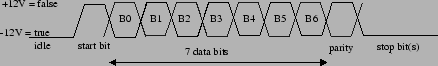
A frame is a complete and nondivisible packet of bits. A frame includes both information (e.g., data and characters) and overhead (e.g., start bit, error checking and stop bits). In asynchronous serial protocols such as RS-232, the frame consists of one start bit, seven or eight data bits, parity bits, and stop bits. A timing diagram for an RS-232 frame consisting of one start bit, 7 data bits, one parity bits and two stop bits is shown below in figure 24. Note that the exact structure of the frame must be agreed upon by both transmitter and receiver before the comm-link must be opened.
Most of the bits in a frame are self-explanatory. The start bit is used to signal the beginning of a frame and the stop bit is used to signal the end of a frame. The only bit that probably needs a bit of explanation is the parity bit. Parity is used to detect transmission errors. For even parity checking, the number of 1's in the data plus the parity bit must equal an even number. For odd parity, this sum must be an odd number. Parity bits are used to detect errors in transmitted data. Before sending out a frame, the transmitter sets the parity bit so that the frame has either even or odd parity. The receiver and transmitter have already agreed upon which type of parity check (even or odd) is being used. When the frame is received, then the receiver checks the parity of the received frame. If the parity is wrong, then the receiver knows an error occurred in transmission and the receiver can request that the transmitter re-send the frame.
In cases where the probability of error is extremely small, then it is customary to ignore the parity bit. For communication between the MicroStamp11 and the host computer, this is usually the case and so we ignore the parity bit.
The bit time is the basic unit of time used in serial communication. It is the time between each bit. The transmitter outputs a bit, waits one bit time and then outputs the next bit. The start bit is used to synchronize the transmitter and receiver. After the receiver senses the true-false transition in the start bit, it waits one half bit time and then starts reading the serial line once every bit time after that. The baud rate is the total number of bits (information, overhead, and idle) per time that is transmitted over the serial link. So we can compute the baud rate as the reciprocal of the bit time.